Keypad access
The System Menu offers selections related to the instrument, connectivity to other instruments, and application interaction with the Windows OS. You can access it from either the keypad or the multi-touch display. Choices are described below:
Keypad access
 Multi-touch access
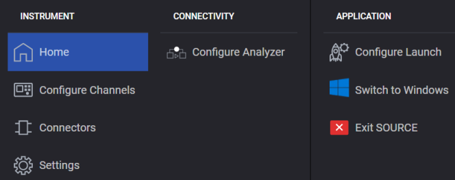
Returns you to the work-flow based block diagram for configuring the generation of signals. Work-flow begins with Signal configuration of the instrument’s baseband on the left, proceeds to Adjustments of the signal, next Output Modulation is applied, followed by the RF Output settings.
For instruments with more than one channel, opens the Configure Channels dialog where you can select from Independent, 2 Tx Coherent, and Bonded configurations, depending on your measurement use case.
Opens the Connectors screen where you can configure the instrument's physical connectors, such as Trigger Input, Trigger Output, and Event Connectors. Applies to the M9484C only.
Opens the Instrument Settings screen.
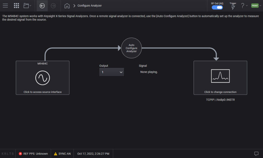
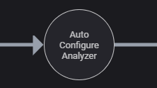
This opens the Configure Analyzer screen for performing generation-to-analysis workflow. VXG signal generators work with Keysight X-Series signal analyzers with application software version x.24.00 or greater. Once a remote signal analyzer is connected, select Auto Configure Analyzer to automatically setup the analyzer to measure the desired signal from the source.
|
GUI Location |
System Menu > Configure Analyzer |
|
Initial S/W Revision |
A.01.00 |
|
Modified S/W Revision |
A.08.00 |
The Remote Instrument screen provides settings for remotely connecting to the Keysight X-Series signal analyzer. The default values for the signal analyzer are pre-populated. Refer to your signal analyzer if the values are different from the default.
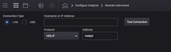
Select a LAN or USB physical communication connection to the analyzer.
Set LAN Address
Enter the Hostname or IP Address of the analyzer. the LAN address is saved during Save User Preset, allowing you to use User Preset to easily restore the address after startup.
Set Protocol
The values of the protocol settings are standard values for the Keysight X-Series signal analyzers. Changes to the values persist across power-cycling and are not changed by Preset. Use Restore System Settings to Default to return the values to their defaults. The protocol in use much match the setting in the analyzer’s configuration.
The default protocol is HiSLIP which has the highest throughput of the LAN choices.
After connecting your device to a USB port, select it from the drop-down menu. You can also refresh the list of USB connected devices, if necessary.
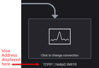
Use this immediate action to check the communication connection to the analyzer. If successful, a message briefly appears and the VISA address is displayed below the ![]() analyzer block in the Configure Analyzer screen. If unsuccessful, a message briefly appears and is logged in the message queue.
analyzer block in the Configure Analyzer screen. If unsuccessful, a message briefly appears and is logged in the message queue.
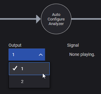
On instruments with more than one channel, you indicate which channel is directed to the signal analyzer.
|
GUI Location |
System Menu > Configure Analyzer > Output Channel |
|
SCPI Command |
[:SOURce]:SCONfigure:OUTPut <channel> [:SOURce]:SCONfigure:OUTPut? |
|
SCPI Example |
SCON:OUTP 1 |
|
Notes |
The maximum selection is based on the configuration of the instrument. Use the query SOUR:RF:COUN? to determine the maximum value for the instrument being controlled. |
|
Preset |
1 |
|
Min |
1 |
|
State Saved |
Yes |
|
Initial S/W Revision |
A.01.00 |
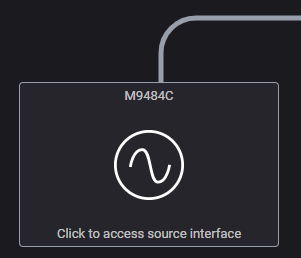
The diagram for the VXGs lists the configuration of the Signal and Frequency for each channel. Selecting the source diagram returns to the generator’s main screen.
Select the Auto Configure Analyzer control to send the signal generator’s settings to the signal analyzer.
Minimizes the VXG signal generator application, allowing you to interact with the Windows desktop. The application continues to run and signals continue to play on any channel that has the RF Output On.
Closes the VXG signal generator software. All signals are disabled and the RF Output is turned Off on all channels.